Hello,
I just wanted to post this for anyone who needs a hard wired power supply attached to to your wireless transmitter.
I have a table saw and it’s powered by a VFD which directly controls the motor. I am using the 202U kit on the multifunction inputs as the on off switch. The 202U worked great right out of the box.
However in my case I wanted a transmitter to install inside the Table saw mounted on off switches so i could run the saw normally from the saw itself.
Please bear in mind modifications to your remote are unsupported by the manufacturer and I’m sure, void the ability to return or warranty the remote so perform these modifications at your own risk.
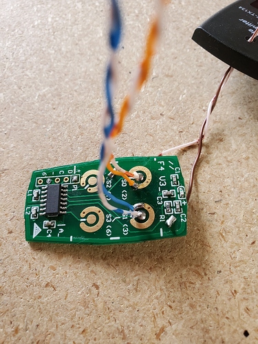
See below photos. I started by removing the PCB from the case, I then removed the battery.
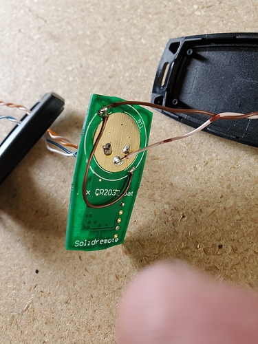
Once the battery was removed, using a soldering iron I removed battery terminal cover plate. Please note it has two solder joints.
I then replaced that with a jumper, to go to both sides of the PCB, as both sides of the circuit will need power (please note the short brown jumper) on one side of the PCB I attached a lead as well as the jumper that is the positive lead. I then using 24 gauge wire pushed the negative lead through the PCB using one of the provided holes on the negative side of the battery surface of the PCB. With both those leads soldered in place, I turn to the PCB over. In my case, I only needed leads for button A and button B. I soldered leads to the outer ring, the pcb has holes and allowed me to push a 24 gauge wire through the PCB so that it can be soldered on both sides.
The other side of the lead was then attached to the center of the button plate. Please be careful if you get solder between the outer and inner rings you will create a short circuit which will then no longer allow the push button to cycle properly and will always be on.
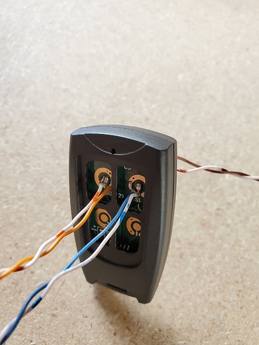
Using a multimeter test your leads to ensure that you do not have any short circuits between your push buttons or your positive and negative battery terminals. I drilled a small hole in the back of the fob casing and ran the positive and negative wires out the back. I ran the activation leads up to their switches by running up through the a/b holes provided on the front casing I reused the old fob case for protection of the board while it was installed in the switch box.
Attach your leads to a 3v battery via the battery leads. It is polarity specific so please ensure proper polarity. Cr123, AA or AAA battery packs should work well depending on how much space you have.
Then you can attach the leads to the push buttons, youll need two normally open (NO) switches. This would then give you the ability to actuate those push buttons via physical switches.
Good luck on your projects, Hope this helps somebody else!


